
VFR Voltmeter Installation
The Infamous Regulator/Rectifier Failure
The Honda VF and VFR prior to model year 2000 had one design flaw . . . the voltage regulator/rectifier. Read some about it here. If you ride a pre-2000 VFR, you owe it to yourself to install a voltmeter to monitor the health of your charging system. After two R/R failures on two separate Honda V-4s, I'll never be without one on a motorcycle again! This page shows how I installed my voltmeter on my '94 VFR.
Which Type of Meter?
I installed an LED voltmeter bought directly from Datel as part of a group buy I put together. In the past, I've also used an LCD meter from I4C. This is essentially a Datel meter pre-wired for the bike. It was a nice unit -- the only drawback is that you can't see it at night. When my last R/R failed, it was on a week-long trip, and I have not-so-fond memories of having to pull a flashlight out while riding in order to see the meter! Never again. I don't ride at night that much, but even in the day the LED meter is much easier to see.
I chose the unit that displays DC volts to a resolution of 0.01 volts. Some think this is overkill, that the resolution to 0.1 volt is fine. It probably is, but the model with the higher resolution is also significantly more accurate. For the same price, I'll take the accuracy.
The Datel units are waterproof. Other owners have installed automotive-accessory type meters that are nice looking, cheap, and have extra features, but I ride hard for long distances, often for several days at a time, and in all types of weather. I prefer a more robust solution.
Wiring Options
I wired my meter directly to the battery. You could also wire it using an auxiliary power circuit that is only on when the bike is on. I've got an auxiliary power block installed on my VFR, but I prefer the unit directly wired to the battery. That way you have a direct measurement of the voltage at the battery -- without the signal going through a series of connectors, fuses, and relays. The downside of this setup is that the meter is always on, drawing power. Personally, I'm not concerned about the LED meter discharging the battery. The draw is low -- rated at 13 mA max. As long as I ride every couple of weeks, this should be no problem. (Note: I've since changed - I now run off the fuse block. No particular reason, but I wanted to see if there was any voltage drop for all the connectors. Voltage drop proved negligible).
Parts List
Tools Needed
Step-by-Step Procedure
I was able to practice the installation on a spare upper fairing piece I had lying around, which is off-white in the photos you'll see. A fortunate benefit of an unfortunate incident, as it were!
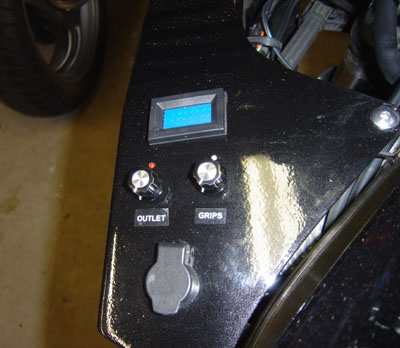
1. Select the location. I chose the flat area of the upper left fairing as seen below. Note the auxiliary power outlet for an electric vest, and Heat-trollers for vest and grips. (Funky labels now gone.)
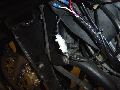
2. Make the Harness. I made a two-piece harness so I could easily disconnect it if I need to remove the fairing in order to service the bike. It's not strictly necessary, but will make installation a whole lot easier. The two-terminal plug was purchased at Radio Shack (see parts list above). The other wire terminals are available at Radio Shack or most auto parts and hardware stores. Pic below shows harness connectors after installation; I ran the wires through some split wire-loom found at any auto parts store. Testing showed no measureable voltage drop after adding the connectors (they were crimped using the right Molex tool, but no solder).
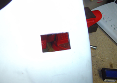
3. Mark the cutout. Datel has a cutting/drilling template on their spec sheet. I ignored that and used the gasket to lightly scribe the cutout area on the fairing panel. Old carpentry trick -- avoid measuring where possible -- use the actual pieces to ensure you've got it right!
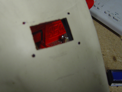
4. Cut the hole. I used a Dremel-type rotary tool with a small cutoff wheel to make the rough cut. CAREFUL! Make sure you don't oversize the cutout. The Datel has a very narrow shoulder to rest on the panel, and you don't want to make it too big or it won't rest on it securely.
When I cut as far as I could with the rotary tool, I used a hacksaw blade to finish the corners (which I couldn't reach with the tool). Then I finished the cutout to shape and size by using a small file..
1. Mark the drill holes. To mark the drill holes for the bezel, I assembled the gasket around the voltmeter, slid it in the cutout, and made a small mark at the holes with a screw. Then drill the holes with a X/X" drill.
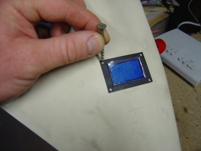
Holes Drilled.
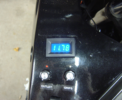
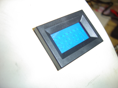
1. Test fit. Here's the assembled meter, with gasket underneath and bezel on top. Even though the location is not totally flat, the bezel still makes for a clean installation.
Questions - just let me know and I'll do my best to answer.
Page last worked on 10-5-2007